GOTT GOTT-LFVAU-01 Laminar Flow Visualization and Analysis Unit
Manufacturer: GOTT Model: GOTT-LFVAU-01 P/N: 843-000 Origin: Malaysia Guarantee: 12 Month - Request a Quotation

- Request a Quotation
- Contact
DEMONSTRATION CAPABILITIES
• Ideal flow around immersed bodies
o Cylinder
o Aerofoil
o Bluff body
• Ideal flow in channels and at boundaries
o Convergent channel
o Divergent channel
o 90 degree bend
o Sudden contraction
o Sudden enlargement
o Replacement of a streamline by a solid boundary
• Ideal flow associated with sinks and sources
o Formation of a Rankine half body
o Formation of a Rankine oval
o Circular streamlines from a doublet
o Superposition of sinks and sources
• Use of streamlines to analyse two dimensional flow
WORKING SECTION
• Width inside moulding: 606mm
• Length of glass plates: 892mm
• Distance between glass plates: 3.2mm
• Sinks/sources: eight tappings in seven positions
WORKING SECTION
2 x rectangles
2 x cylinders
1 x aerofoil
Manuals:
(1) All manuals are written in English
(2) Model Answer
(3) Teaching Manuals
Datasheet
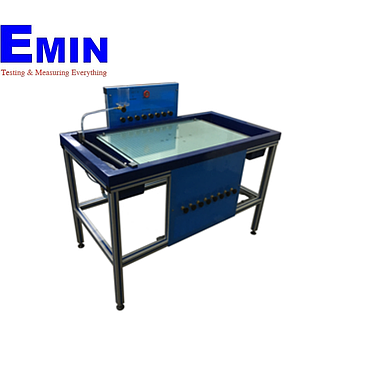
DESCRIPTION
The Laminar Flow Table is an improved version of the classical Hele-Shaw apparatus with the addition of sinks and sources. It consists of two closely spaced sheets of laminated glass, arranged horizontally on a glass fibre moulding. An inlet tank and discharge tank are incorporated in the moulding, which is supported on a floor standing, metal frame. Three adjustable feet enable rapid levelling of the flow table.
Eight miniature tapings, which may be used as sinks or sources are arranged about the centreline of the lower glass plate in a cruciform configuration. A doublet (a sink and source in close proximity) is located at the centre of the pattern. A system of pipes, valves and manifolds enables any combination of the sinks and sources to be used. A row of control valves mounted above the flow table is used to adjust the flow through each individual source. A row of sink control valves is used to adjust the flow through each individual sink.
A row of hypodermic needles attached to a manifold is positioned between the glass plates at the inlet edge. To visualise the flow of water between the glass plates, dye is injected through the equally spaced needles. The position of each streamline is clearly indicated by the dye, which is supplied from a reservoir fitted with a flow control valve. A black gratitude on a white background is printed on the underside of the lower glass plate to aid visualisation of the streamlines.
The patterns created by the potential flow may be recorded by tracing on the top glass sheet or by photography if required. A diffuser in the inlet tank and an adjustable weir plate in the discharge tank help to promote a uniform flow of water. Valves are incorporated in the base of these tanks to aid draining. The flow of water is controlled by an inlet flow control valve. A pressure regulator reduces the mains water pressure and helps to minimise variations in flow.
The top glass plate may be raised at the front edge and retained in this position to enable models to be placed in the working section. A set of models are supplied for basic flow studies. These models are manufactured from plastic sheet and are trapped in the required position when the top glass plate is lowered. Alternative models can be fabricated from any convenient material and used to investigate the associated flow patterns.
- Quality Engagement
- Easy change and return
- Delivery Avaliable
- Favorable payment