
ETEK DA-2000 Digital and Analog Communication Trainer (9 Modules)
Module One: ETEK DA-2000-01
Chapter 1: RF Oscillator Circuits Design
Experiment 1: Colpitts Oscillators Circuit
Type of Signal: Oscillation Frequency: 1 MHz ~ 10 MHz.
Experiment 2: Hartley Oscillators Circuit
Type of Signal: Oscillation Frequency: 500 kHz ~ 2 MHz.
Chapter 2: Second Order Filter Circuits Design
Experiment 1: Second Order LPF Circuit
Type of Signal: Low-pass -3 dB Frequency: 1 kHz ~ 10 kHz.
Experiment 2: Second Order HPF Circuit
Type of Signal: High-pass -3 dB Frequency: 800 Hz ~ 8 kHz.
Experiment 3: Second Order BPF Circuit
Type of Signal: Center Frequency: 6 kHz; Bandwidth: 10 kHz.
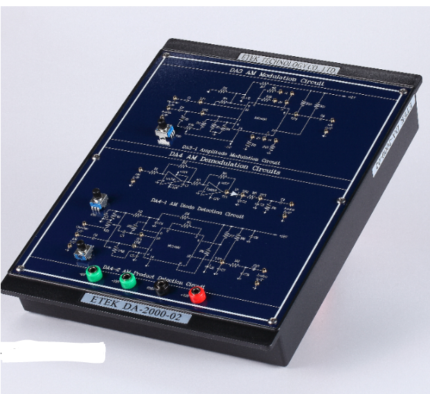
Module Two: ETEK DA-2000-02
Chapter 3: Amplitude Modulation Circuit Design
Experiment 1: Amplitude Modulation Circuit
Type of Signal: Carrier Signal: 500 kHz ~ 3 MHz; Audio Signal Frequency: 1 kHz ~ 3 kHz.
Chapter 4: Amplitude Demodulation Circuit Design
Experiment 1: AM Diode Detection Circuit
Type of Signal: Carrier Signal: 200 kHz ~ 300 kHz; Audio Signal Frequency: 1 kHz ~ 3 kHz.
Experiment 2: AM Product Detection Circuit
Type of Signal: Carrier Signal: 500 kHz ~ 3 MHz; Audio Signal Frequency: 1 kHz ~ 3 kHz; Modulation Index: 50 %.
Module Three: ETEK DA-2000-03
Chapter 5: Frequency Modulation Circuit Design
Experiment 1: The Specification Measurement of MC1648 VCO
Type of Signal: Oscillation Frequency: 2 MHz ~ 3 MHz.
Experiment 2: MC1648 FM Circuit
Type of Signal: Carrier Signal: 2.8 MHz; Audio Signal Frequency: 3 kHz ~ 8 kHz.
Experiment 3: The Specification Measurement of LM566 VCO
Type of Signal: Oscillation Frequency: 1 kHz ~ 30 kHz.
Experiment 4: LM566 FM Circuit
Type of Signal: Carrier Signal: 20 kHz; Audio Signal Frequency: 1 kHz ~ 5 kHz.
Chapter 6: Frequency Demodulation Circuit Design
Experiment 1: The Specification Measurement of LM565 PLL
Type of Signal: Nature Frequency: 0.6 kHz ~ 77 kHz; Phase Locked Range: 1.1 kHz ~ 3.9 kHz; Phase Caught Range: 1.2 kHz ~ 3.8 kHz.
Experiment 2: The Specification of Voltage and Frequency for LM565 PLL
Type of Signal: Input Signal Frequency: 0.5 kHz ~ 23.5 kHz;
Output Voltage: 3V ~ 4.5V.
Experiment 3: LM565 Phase Locked Loop Circuit
Type of Signal: Nature Frequency: 20 kHz; Audio Signal Frequency: 1 kHz ~ 3 kHz.
Experiment 4: FM to AM Discriminator Circuit
Type of Signal: Nature Frequency: 2 MHz; Audio Signal Frequency: 1 kHz ~ 3 kHz.
Module Four: ETEK DA-2000-04
Chapter 7: Analog to Digital Converter Circuit Design
Experiment 1: ADC0804 ADC Circuit
Type of Signal: Resolution: 8 bits; Analog Input Voltage: 0 V ~ 5 V.
Experiment 2: ADC0809 ADC Circuit
Type of Signal: Resolution: 8 bits; analog Input Voltage: 0 V ~ 5 V;
Clock Frequency: 120 kHz.
Chapter 8: Digital to Analog Converter Circuit Design
Experiment 1: Unipolar DAC 0800 DAC Circuit
Type of Signal: Digital Input: 8 bits; Analog Output: 0 V ~ 5 V; Step Value: 0.019V.
Experiment 2: Bipolar DAC 0800 DAC Circuit
Type of Signal: Digital Input: 8 bits; Analog Output: -5 V ~ 5 V; Step Value: 0.038V.
Module Five: ETEK DA-2000-05
Chapter 9: Pulse Width Modulation Circuit Design
Experiment 1: UA741 PWM Circuit
Type of Signal: Carrier Signal: 1.5 kHz ~ 2 kHz; Audio Signal Frequency: 500 Hz.
Experiment 2: LM566 PWM Circuit
Type of Signal: Carrier Signal: 5 kHz ~ 10 kHz; Audio Signal Frequency: 1 kHz.
Chapter 10: Pulse Width Demodulation Circuit Design
Experiment 1: PWM Demodulation Circuit
Type of Signal: Carrier Signal: 5 kHz ~ 6 kHz; Audio Signal
Frequency: 500 Hz ~ 700 Hz.
Module Six: ETEK DA-2000-06
Chapter 11: Amplitude-Shift Keying Modulation Circuit Design
Experiment 1: ASK Modulation Circuit
Type of Signal: Carrier Signal: 20 kHz ~ 100 kHz; Modulation Signal
Frequency: 1 kHz ~ 10 kHz)
Chapter 12: Amplitude-Shift Keying Demodulation Circuit Design
Experiment 1: ASK Non-coherent Detection Circuit
Type of Signal: Carrier Signal: 20 kHz ~ 100 kHz; Modulation Signal Frequency: 1 kHz ~ 10 kHz.
Experiment 2: ASK Coherent Detection Circuit
Type of Signal: Carrier Signal: 20 kHz ~ 100 kHz; Modulation Signal
Frequency: 1 kHz ~ 10 kHz.
Module Seven: ETEK DA-2000-07
Chapter 13: Frequency-Shift Keying Modulation Circuit Design
Experiment 1: FSK Modulation Circuit
Type of Signal: Space Signal: 1370 Hz; Mark Signal: 870 Hz; Data
Signal: 200 Hz ~ 5 kHz.
Chapter 14: Frequency-Shift Keying Demodulation Circuit Design
Experiment 1: FSK Demodulation Circuit
Type of Signal: Space Signal: 1370 Hz; Mark Signal: 870 Hz; Data
Signal: 200 Hz ~ 5 kHz.
Module Eight: ETEK DA-2000-08
Chapter 15: Phase-Shift Keying Modulation Circuit Design
Experiment 1: PSK Modulation Circuit
Type of Signal: Carrier Signal: 100 kHz; Data Rate: 200 bps; Data
Signal: 100 Hz ~ 1 kHz.
Chapter 16: Phase-Shift Keying Demodulation Circuit Design
Experiment 1: PSK Demodulation Circuit
Type of Signal: Carrier Signal: 100 kHz; Data Rate: 400 bps ~ 1000 bps;
Data Signal: 100 Hz ~ 1 kHz.
Module Nine: ETEK DA-2000-09
Chapter 17: QPSK Modulation Circuit Design
Experiment 1: Bit-splitter Circuit
Type of Signal: Data Rate: 100 bps ~ 1000 bps.
Experiment 2: QPSK Modulation Circuit
Type of Signal: Carrier Signal: 20 kHz; Data Rate: 1000 bps.
Chapter 18: QPSK Demodulation Circuit Design
Experiment 1: Signal-square and PLL Circuit
Type of Signal: Carrier Signal: 20 kHz; Data Rate: 1000 bps.
Experiment 2: QPSK Demodulation Circuit
Type of Signal: Carrier Signal: 20 kHz; Data Rate: 1000 bps.
Get exclusive volume discounts, bulk pricing updates, and new product alerts delivered directly to your inbox.
By subscribing, you agree to our Terms of Service and Privacy Policy.
Direct access to our certified experts