Hall camshaft sensor testing is an important waveform-based task in automotive diagnostic work. A digital oscilloscope allows technicians to observe the sensor signal as engine speed changes, rather than relying only on a static electrical check. This can help provide a clearer view of signal frequency and the timing relationship between camshaft and crankshaft signals.
Using an oscilloscope for Hall camshaft sensor testing
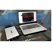
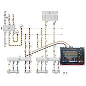
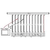
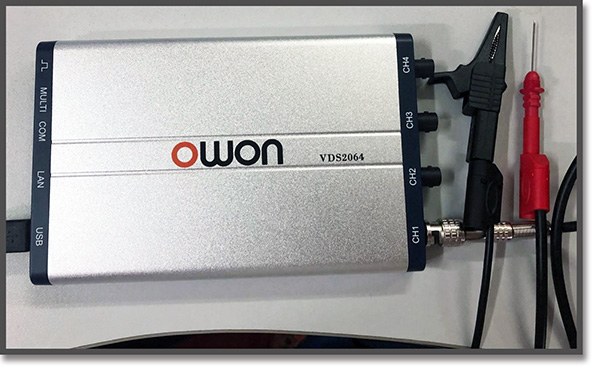
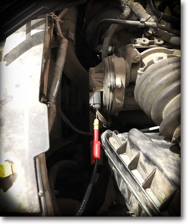
A Hall camshaft position sensor produces a waveform that can be examined with an oscilloscope. In the source procedure, an OWON VDS2064 digital oscilloscope is used with a BNC connection and a dedicated tip probe. The probe’s red connection is placed at the Hall camshaft sensor test point, while the black clip is connected to vehicle ground at a metal location.
Before making connections, technicians should identify the intended test point and a suitable ground point on the vehicle. Keeping the probe and ground connection secure helps make the displayed waveform easier to assess during the measurement.
What to observe in the camshaft sensor waveform
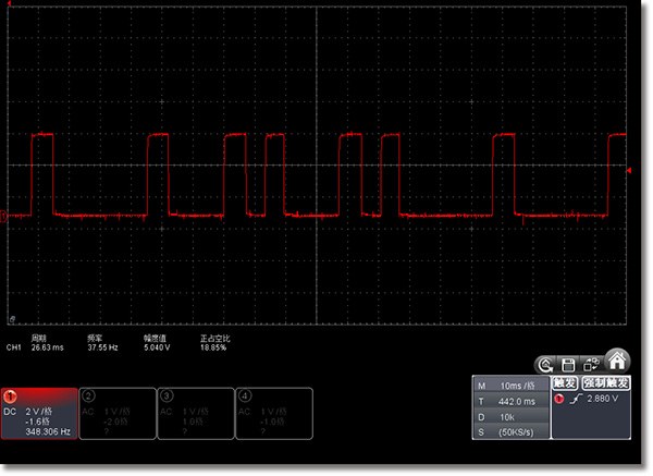
For a Hall sensor, frequency is a key item to check. The camshaft signal can be measured at different engine speeds to observe how the waveform changes. Comparing signals at more than one speed provides a broader view than a single capture taken under one operating condition.
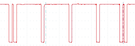
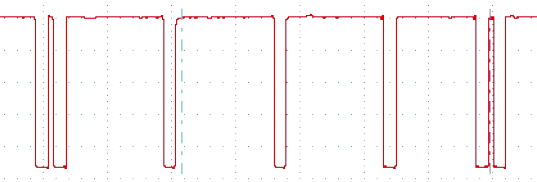
The source material also highlights the phase relationship between the crankshaft and camshaft sensors. Their waveforms include marking teeth, and the tooth-count difference between the relevant markings is expected to remain fixed. A difference of one additional or missing tooth can indicate an incorrect relationship that may affect engine operation.
Compare timing characteristics carefully
Waveform interpretation should focus on the relationship of the signals, not only on whether a signal is present. When examining captures, technicians can compare the position of marking teeth and the repeatability of the pattern. The source examples show measurements at 25 ms/div and 1 V/div, as well as 10 ms/div and 1 V/div.
These time-base settings illustrate that the display can be adjusted to review waveform detail at different scales. The appropriate setting depends on the signal being examined and the level of timing detail required for the diagnostic task.
OWON VDS2064 and VDS Series PC oscilloscopes
The OWON VDS2064 is identified in the source procedure as the digital oscilloscope connected to the Hall camshaft sensor. The source also presents the OWON VDS Series PC oscilloscope as a compact option for automotive maintenance environments, where portability can be useful.
According to the provided product information, the VDS Series includes up to 100 MHz bandwidth, a maximum 1 GS/s real-time sample rate, and a 10M record length. These stated capabilities support waveform acquisition and review during electronic sensor testing.
The listed interface and analysis functions include FFT, X-Y display, and two waveform views on the same screen. Available trigger options are edge, video, slope, pulse, and alternate. The source also lists USB isolation to reduce signal interference and help protect the connected PC, USB bus powering, optional LAN remote control, and an ultra-thin body design.
A practical workflow for automotive diagnostics
A structured workflow can make Hall camshaft sensor testing more consistent. First, connect the probe at the intended sensor point and establish the ground connection. Next, capture the waveform at different engine speeds. Then, review frequency and compare the camshaft waveform with the crankshaft waveform where applicable.
Finally, examine the marking-tooth relationship and check whether the observed timing pattern remains consistent. This approach keeps the diagnostic process focused on the signal characteristics described in the source material: frequency, waveform pattern, and the fixed phase relationship between camshaft and crankshaft signals.
For automotive technicians, an oscilloscope is therefore a useful tool for moving beyond a basic sensor presence check. It makes waveform behavior visible and supports more informed assessment of Hall camshaft position sensor signals.