Materials undergo sudden changes—expanding or contracting—at different rates. Metals, plastics, ceramics, glass, epoxies, and semiconductors do not respond identically to the same thermal fluctuations. The resulting differential movement between material layers generates mechanical stress, which over time can lead to cracking, delamination, bond failure, or electrical parameter drift.
1. Weld cracking
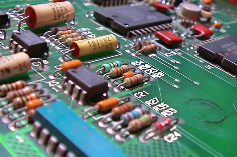
Solder joints are particularly susceptible to damage from repeated thermal cycling, especially in Surface Mount Device (SMD) and Ball Grid Array (BGA) components.
As temperatures rise, the circuit board, component leads, and solder material expand; conversely, they contract as temperatures fall. However, because each material has a different coefficient of thermal expansion, they do not all change dimensions at the same rate.
This disparity generates repetitive tensile and shear forces at the solder joint. Initially, micro-cracks may appear. Over multiple cycles, these cracks propagate, leading to degraded electrical connectivity or complete connection failure.
Common issues include:
+ Intermittent component operation
+ Intermittent loss of connection
+ Increased contact resistance
+ Cracked or broken solder joints
+ Short circuits caused by unintended contact between conductive elements
With BGA components, the problem is even harder to detect because the solder balls are concealed beneath the component body. A product might pass initial testing but fail after undergoing multiple thermal cycles during actual use.
2. Separate PCB inner layers
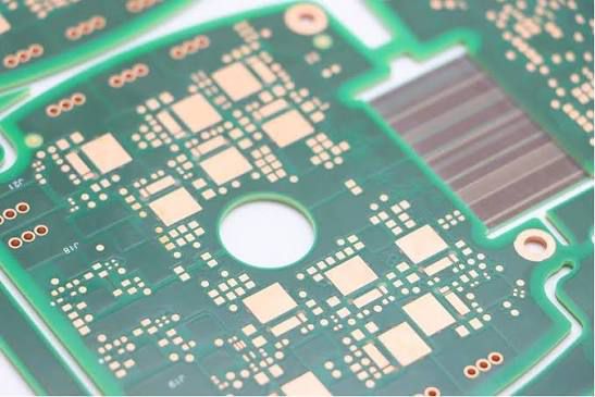
A printed circuit board (PCB) is not a homogeneous block of material; it typically consists of multiple layers of copper, fiberglass, epoxy resin, and insulating materials laminated together.
When subjected to rapid temperature changes, these layers may expand and contract at different rates. If the accumulated stress exceeds the bonding strength between the layers, delamination can occur.
Delamination can lead to:
+ Reduced interlayer bonding
+ Formation of internal voids within the board
+ Weakening of conductive traces
+ Damage to vias passing through multiple circuit layers
+ Increased susceptibility to moisture ingress into the PCB structure
This issue is particularly significant in multilayer boards, where internal defects may not be easily detected through external inspection.
3. Component casing crack
The protective casings of ICs, capacitors, resistors, and various other components may be made of plastic, ceramic, or glass. These materials respond differently to temperature fluctuations.
Thermal shock can cause cracks to form in component casings. Initially, these cracks may be minute and not cause immediate component failure; however, they can create pathways for moisture and environmental contaminants to penetrate the interior.
Over time, this can lead to:
+ Corrosion of conductive structures
+ Degradation of internal protective layers
+ Electrical leakage
+ Alteration of electrical characteristics
+ Component failure
For hermetically sealed components, resistance to moisture ingress is a critical factor in long-term durability. Consequently, even minor cracks resulting from thermal stress can eventually lead to component failure.
4. Broken internal wire connection within the component
Inside many microchips, microscopic wires connect the semiconductor chip to the component's external pins. Although these connections are tiny, they are subjected to expansion and contraction forces during every thermal cycle.
Differential movement between the wire, the semiconductor chip, and the surrounding package can generate stress at the connection points. Repeated temperature fluctuations can cause the wires to:
+ Break
+ Detach from the connection point
+ Suffer reduced electrical conductivity
This type of failure often cannot be detected through standard visual inspection. The component may appear perfectly normal yet fail to operate reliably due to compromised internal connections.
5. Delamination of coating and bonding material
Thermal shock can also degrade the materials used to protect or bond components.
Some examples include:
+ Protective coatings on PCBs peeling or cracking
+ Degradation of adhesives bonding components together
+ Thermal interface materials separating from contact surfaces
+ Cracking of encapsulation layers
The cause is often linked to differences in thermal expansion between the bonding material and the surfaces to which it adheres. With each temperature change, the two materials may expand or contract at different rates, creating repetitive stress at the interface. If the adhesive or coating delaminates, the component's protective, insulating, or heat-transfer capabilities may be compromised.
6. Changes in electrical parameters and performance degradation
Not all effects of thermal shock result in visible cracks or damage. Some components may remain functional, yet their parameters deviate from their original specifications.
For instance, temperature fluctuations can affect:
+ The oscillation frequency of quartz crystals
+ Reference voltage
+ Resistance values
+ Capacitance
+ Leakage current
+ Semiconductor component characteristics
After multiple thermal cycles, certain parameters may "drift" gradually shifting away from their initial values. In devices requiring high stability, even a minor deviation can impact operational performance.
This is why a component does not necessarily have to fail completely to be considered non-compliant. If parameters fall outside permissible limits, the product may still be rejected, even in the absence of obvious external signs of damage.
7. Why can thermal shock cause a failure to appear after some time?
A single thermal cycle does not necessarily cause immediate failure; many defects arise from a cumulative process.
Each time the product transitions between low and high temperatures, its internal components undergo expansion and contraction. Stress can concentrate at vulnerable points such as:
+ Solder joints
+ Component corners
+ Interfaces between different materials
+ PCB vias
+ Wire bond points
+ Contact areas between coatings and substrates
Over multiple cycles, micro-cracks or weakened bond interfaces can progress to the point of causing a distinct failure.
This is why thermal shock testing is frequently used to accelerate this process under controlled conditions. Instead of waiting for the product to fail after prolonged real-world use, manufacturers can subject test samples to predefined thermal cycles to evaluate the durability of components and the product structure.
How can damage caused by thermal shock be detected?
The inspection method depends on the component type and the specific failure mode being investigated. Common assessment approaches often include:
- Visual inspection to detect cracks, delamination, or deformation
- Measurement of electrical parameters before and after testing
- Circuit continuity checks
- Solder joint inspection
- X-ray imaging for structures that are difficult to observe directly
- Cross-sectional analysis to pinpoint internal failure sites
Typically, initial parameters of the test sample are measured; the sample then undergoes thermal cycling under specified conditions, followed by a re-examination to detect any changes.
To rapidly simulate transitions between different temperature environments, laboratories often use thermal shock chambers. This equipment cycles the test sample through varying temperature zones under controlled conditions, thereby evaluating the component's resilience to repeated thermal fluctuations.
KOMEG thermal shock chambers are used to create conditions involving rapid temperature changes between different temperature zones. Depending on testing requirements, businesses can choose from models with various temperature ranges and capacities, such as:
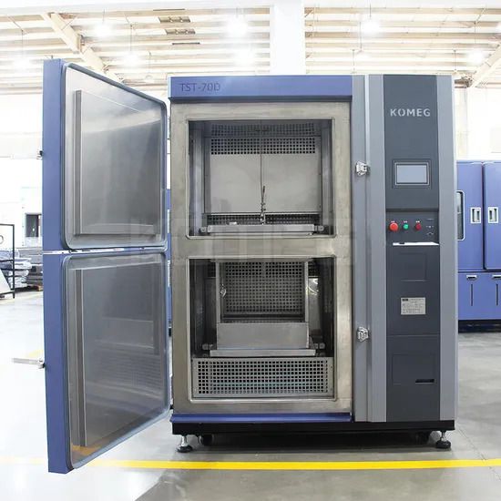
KTS-72A: temperature range -40°C to +150°C, 72L capacity
KTS-100A: temperature range -40°C to +150°C, 100L capacity
KTS-200A: temperature range -40°C to +150°C, 200L capacity
KTS-252A: temperature range -40°C to +150°C, 252L capacity
KTS-300A: temperature range -40°C to +150°C, 300L capacity
KTS-480A: temperature range -40°C to +150°C, 480L capacity
KTS-72B and KTS-100B: temperature range -55°C to +150°C
Conclude
Thermal shock can cause various types of damage, ranging from solder joint cracking, PCB delamination, component casing cracks, and broken interconnects to coating delamination and shifts in electrical parameters. Notably, these defects do not always manifest immediately after the initial temperature change.
For products operating in environments with significant temperature fluctuations, thermal shock testing helps identify early weaknesses related to materials, structural integrity, and internal component connections. Based on the test results, manufacturers can evaluate the product's durability before proceeding to mass production or actual deployment.