A single measurement only reflects the condition of a machine at the time of inspection. Data collected continuously or at regular intervals allows technicians to identify changes, compare current conditions with the equipment's historical data, and determine when intervention is required. This approach helps reduce unexpected breakdowns and prevent recurring failures.
Below are some of the most common problems encountered during the operation and maintenance of industrial equipment.
Motor Overheating Despite Continued Operation
Motor overheating can result from both electrical and mechanical causes. Overloading increases current, which in turn increases losses in the windings. Voltage imbalance between phases can also cause uneven current distribution and excessive heat generation. On the mechanical side, bearing friction, shaft misalignment, or restricted cooling can cause the temperature to rise.
Therefore, measuring temperature alone is not sufficient to determine the root cause. The inspection process should combine voltage, three-phase current, and temperature measurements at locations where heat generation is likely to occur. If abnormal vibration is detected, the bearings, coupling, and alignment of the drive system should also be inspected.
Measurement values help determine the appropriate corrective action. Current exceeding the rated value requires an assessment of the load and operating conditions. Differences in current between phases require checking the power supply, connections, and windings. Heat concentrated around a bearing, combined with increased vibration, indicates that the mechanical components should be inspected.
After corrective action, the motor should be retested under equivalent load conditions. The results should be stored together with the pre-maintenance data to evaluate the improvement and monitor the condition during subsequent inspection cycles.
Inverter Faults, PLC Failures, or Unexpected Robot Shutdowns
Faults involving inverters, PLCs, and robots can be difficult to trace when the equipment stops only briefly and resumes operation after a reset.
An inverter may experience faults caused by overcurrent, overvoltage, undervoltage, overheating, or abnormalities in the motor and load. For PLCs and robots, interruptions in the control power supply or short-duration voltage drops can also cause the equipment to stop.
Measuring voltage with a multimeter at the time of inspection often fails to capture fluctuations that occurred earlier. By the time technicians reach the equipment, the power supply may have already returned to normal.
In such cases, a power quality analyzer and recorder can be used to monitor the system during operation. Events such as voltage sags, swells, short interruptions, transients, and voltage fluctuations can be recorded together with the time at which the fault occurs. This data allows technicians to correlate electrical events with the moment when an inverter, PLC, or robot stopped.
If the fault coincides with a voltage sag, the power supply, wiring, switching equipment, and high-power loads within the same system should be inspected. Once the power supply has been confirmed to be stable, troubleshooting can then focus on the inverter, motor, load, and configuration parameters.
This approach helps distinguish faults originating from the power supply from those occurring in the control equipment or load, rather than relying solely on the displayed error code.
Hot Spots at Cable Terminals and Connection Points in Electrical Panels
In electrical panels, abnormal temperatures at cable terminals, terminal blocks, or switching devices are often associated with increased contact resistance. When the system is under load, a location with high contact resistance generates heat. The heat can degrade the contact material, which further increases resistance and heat generation.
Key areas to inspect include cable lugs, terminal blocks, contactors, circuit breakers, busbars, and high-load connections.
A thermal imaging camera can be used to scan the entire electrical panel while the system is operating, helping identify abnormally hot areas. The results should be compared between phases, similar components, and the load conditions at the time of inspection.
Detecting a hot spot is only the first step in narrowing down the problem. Technicians should check the load current, condition of the connections, tightness of connection points, and contact quality before deciding whether repair or component replacement is necessary.
After corrective action, the electrical panel should be inspected again under equivalent load conditions. Comparing thermal images taken before and after maintenance helps confirm that the hot spot has been resolved rather than relying solely on visual inspection.
Increasing Vibration in Rotating Equipment
Imbalance, misalignment, mechanical looseness, bearing damage, and transmission problems can all cause vibration levels to increase.
For pumps, fans, motors, gearboxes, and other rotating equipment, the machine may continue operating without producing enough noise or vibration to be detected through ordinary sensory inspection.
Monitoring vibration at fixed measurement points helps establish baseline data for each piece of equipment. When vibration levels increase, frequency analysis can be used to identify the source of excitation and distinguish between imbalance, misalignment, mechanical looseness, and bearing-related problems.
For example, an increase in vibration accompanied by a rise in bearing temperature is a basis for checking lubrication and bearing condition. Vibration clearly related to rotational speed requires checking the balance and alignment of the system.
After alignment, balancing, or bearing replacement, vibration levels should be measured again. If the data continues to increase after a short period, the underlying cause of the failure should be investigated again rather than simply replacing components according to a fixed schedule.
Declining Pneumatic Pressure Due to Difficult-to-Locate Air Leaks
Compressed-air leaks can occur at couplings, valves, hoses, quick-connect fittings, or pipe connections. Small leaks may not stop the production line, but they force the system to supply additional compressed air to maintain operating pressure.
In factories with a large number of machines, environmental noise makes it difficult to locate leaks by listening alone. When pressure remains within the normal operating range, the problem becomes even more difficult to detect through conventional inspections.
Ultrasonic leak detection equipment can identify the area where a leak signal originates while the system is still operating. After tightening a connection, replacing a hose, or repairing a valve, the location should be inspected again to confirm that the leak has been eliminated.
For systems with multiple points of consumption, data on the location and condition of leaks should be recorded by area. Locations where leaks have previously occurred can be added to the periodic inspection schedule, helping control compressed-air losses and energy consumption.
Insulation Resistance Decreasing Over Time
Motors, cables, and electrical equipment operating in environments with high temperatures, dust, or humidity are at risk of insulation degradation over time. When insulation resistance decreases, the underlying cause should be identified before deciding whether to clean, dry, repair, or replace the equipment.
Moisture, dirt, material aging, and damage to insulation layers can all affect measurement results. A low value at a single point in time is not sufficient to determine the rate of deterioration. A series of measurements collected over multiple inspections provides a clearer view of the trend.
Periodic insulation resistance measurements, with results recorded for each piece of equipment, provide a basis for comparison between maintenance cycles. When the value continues to decline, the inspection frequency can be increased and the cause identified before an insulation failure occurs.
After corrective action, measurements should be repeated using the same method and test conditions to verify the result. Post-maintenance data should then be used as the reference value for the next inspection.
Predictive Maintenance Based on Measurement Data
Predictive maintenance is not simply about detecting machines that are about to fail. The goal is to determine how equipment is changing, where the change is occurring, and which underlying causes need to be addressed before a failure affects the production line.
An overheating motor requires a combination of electrical and mechanical data. An inverter or robot that stops unexpectedly requires an analysis of the events that occurred before the failure. A hot spot in an electrical panel requires an assessment of the load and connection condition. Increasing vibration requires analysis of the source of the vibration. Air leaks require precise identification of the leakage location. Declining insulation resistance requires trend monitoring and investigation of the cause of deterioration.
Each inspection result should be linked to the equipment's maintenance history. Once sufficient data has been collected, technicians can compare temperature, vibration, current, insulation resistance, and other relevant parameters across different operating cycles.
The maintenance process can be organized into a closed loop:
Detect abnormal conditions → Record operating conditions → Perform measurements → Analyze the root cause → Repair → Verify through follow-up measurements → Monitor the trend
Fluke Equipment for Industrial Maintenance Inspection and Diagnostics
To move from manual inspection to data-driven maintenance, technicians can combine different measurement methods depending on the type of abnormality. Fluke Ti4010U, TiS75 PRO, and TC03A support thermal inspection, helping technicians quickly identify abnormal hot spots in motors, electrical panels, cable terminals, terminal blocks, and other electrical equipment.
For power-related problems, Fluke 1777 can record events such as voltage sags, swells, interruptions, transients, and harmonics, allowing technicians to correlate electrical events with the time when an inverter, PLC, or robot stops.
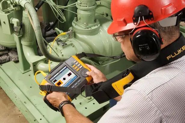
Fluke 810 supports vibration analysis and diagnosis of common problems such as imbalance, misalignment, mechanical looseness, and bearing damage. It is suitable for motors, fans, pumps, gearboxes, and other drive systems.
In compressed-air systems, Fluke ii915 helps detect and locate air leaks using acoustic imaging technology, even in noisy industrial environments. The device also supports leak quantification and cost estimation through LeakQ™.
In addition to condition-monitoring methods, Fluke 754 can be used to simulate process signals such as current, voltage, temperature, and pressure, supporting the testing and calibration of measurement instruments in automation systems.
Monitoring measurement data and trends helps identify the causes of potential failures at an early stage, ensuring continuous and safe system operation, optimizing performance and repair costs, and extending equipment service life.