
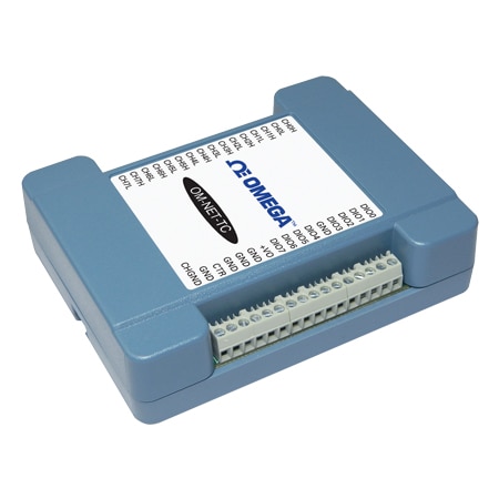
OMEGA OM-NET-TC 8-Channel Thermocouple Input Ethernet Data Acquisition Module (Thermocouple, Digital, Thermocouple: 8 DIFF, Digital: 1, Temperature Alarms: 8, Counter: 1, Screw Terminal)
CMRR: 110 dB
NMRR: 75 dB
Width: 82.8 mm
Height: 29 mm
Length: 117.9 mm
Memory: EEPROM: 4096 bytes
Weight: 0.4 kg
Accuracy: ± 0.006%
Bandwidth: 10 Hz
Isolation: Isolation Between Any Thermocouple Input Channel and Digital/Chassis Ground: 500 Vdc absolute max
Alarm Note: Number of Alarms: 8 (one per digital I/O line) Alarm Functionality: Each alarm controls its associated digital I/O line as an alarm output. When an alarm is enabled, its associated I/O line is set to output and driven to the appropriate state determined by the alarm options and input temperature. The alarm configurations are stored in non-volatile memory and loaded at power on Alarm Input Modes: • Alarm when input temperature ≥T1, reset alarm when input temperature T2 • Alarm when input temperature is T2 • T1 and T2 may be independently set for each alarm Alarm Error Modes: • Alarm on temperature reading only • Alarm on temperature reading or open thermocouple error • Alarm on thermocouple error only Alarm Output Modes: • Disabled, digital I/O line may be used for normal operation • Enabled, active high output (DIO line goes high when alarm condition is met) • Enabled, active low output (DIO line goes low when alarm condition is met) Alarm Latency: 1 second (Alarm settings are applied when changed and at power-ON. Temperatures are converted on enabled channels and processed for alarm conditions regardless of the communications connectivity)
Input Type: Thermocouple, Digital
Wire Gauge: 30 to 16 AWG
Warm Up Time: 20 min
Digital Input: Digital: Low = –0.5 Vdc
Output Signal: Digital, Alarm
Sampling Rate: 4 Hz (4 updates/second)
Data Interface: Ethernet
Digital Output: 10 mA max
LED Indicators: Power LED (Top),Activity LED (Bottom),Ethernet Connector LEDs Left, Green: Link/activity indicator
Supply Current: 177 mA
Supply Voltage: 5 Vdc
Analog I/O Note: Analog Input Note: THERMOCOUPLE INPUT ;A/D Converter Type: Delta-Sigma;A/D Resolution: 24-bit;Number of Channels: 8 differential channels;Isolation Between Any Thermocouple Input Channel and Digital/Chassis Ground: 500 Vdc absolute max;Channel Configuration: Software selectable for thermocouple types J, K, T, E, R, S, B, N (factory default configuration is type J). Channel configuration is stored on EEPROM external to the isolated microcontroller by the firmware whenever any item is modified. Modification is performed by commands issued from an external application, and the configuration is made non-volatile through the use of the EEPROM.;Differential Input Voltage Range: ±0.128V (calibration is performed at ±70 mV);Absolute Maximum Input Voltage (Between any Two TCx Inputs): ±25V (power on), ±25V (power off);Differential Input Impedance: 40 MΩ;Input Current; Open Thermocouple Detect ;Disabled: 1 nA; Open Thermocouple Detect ;Enabled: 65 nA;Common Mode Rejection (fin = 50 Hz or 60 Hz): 110 dB;Noise Rejection (fin = 50 Hz or 60 Hz): 75 dB;Input Bandwidth: 10 Hz;Crosstalk Between Any Two Thermocouple Inputs: -90 dB;Sample Rate: 4 Hz max (per channel). The enabled thermocouple inputs are continuously converted at the maximum A/D converter rate. If channels are enabled and have an open thermocouple connection the sampling rate will be lower.;Input Noise: 250 nV rms;Gain Error: 0.006% FSR;Offset Error: 3 μV;Measurement Sensitivity (Smallest Change in Temperature That Can Be Detected): ;Thermocouple Type J,K,T,E,N: 0.09°C;Thermocouple Type R,S: 0.11°C;Thermocouple Type B: 0.13°C;Warm-Up Time: 20 minutes min;Open Thermocouple Detect Response Time: 1 s;CJC Sensor Accuracy (0 to 45°C): ±0.20°C typ, ±0.40°C max;
Input Type Note: Thermocouple: J, K, T, E, R, S, B, N
Digital I/O Note: DIGITAL I/O Digital Type: 5V TTL input/ CMOS output Number of I/O: One port of 8 bits, shared with temperature alarms Configuration: Each bit can be independently configured for input or output Pull-Up Configuration: All pins pulled up to 5V using 47 K resistors (default). Can be changed to pull-down using an internal jumper Digital I/O Transfer Rate (System Paced): 100 to 5000 port reads/writes or single bit reads/writes per second typ, on local network. This is the typical throughput when the device and host are both connected by Ethernet to the same local network. The throughput can vary significantly, and typical throughput is not guaranteed if a wireless connection is involved or data is sent over the internet Alarm Functionality: Any combination of DIO bits may be configured to become outputs and go to defined values when an Ethernet connection with a host is established or lost Power On and Reset State: All bits are input unless the alarm functionality is enabled for them Input High Voltage Threshold: 2.0V min Input High Voltage Limit: 5.5V absolute max Input Low Voltage Threshold: 0.8V max Input Low Voltage Limit: -0.5V absolute min, 0 V recommended min Output High Voltage: 4.4V min (IOH = -50 µA), 3.76V min (IOH = -24 µA) Output Low Voltage: 0.1V max (IOL = 50 µA), 0.44V max (IOL = 24 µA) Power On and Reset State: Input;Cross talk: -90 db;Schmitt Trigger Hysteresis: 0.6V min, 1.7V max
Pull-up Resistor: 47 kΩ
Output Resolution: Digital: 8-bits, Temperature Alarms: 8
Relative Humidity: 0 to 90% RH non-condensing
Supply Power Note: External Power Supply: 5V, 1A (via included AC adapter) Supply Current (Quiescent Current): 177 mA typ (this is the total quiescent current requirement for the device that includes the LEDs and does not include any potential loading of the digital I/O bits or +VO terminal User Output Voltage Range (Available at +VO Terminal): 4.40V min to 5.25V max, assumes supplied AC adapter is used User Output Current (Available at +VO Terminal): 10 mA max
Input Voltage Note: Absolute Maximum Input Voltage: ±25V (Power On), ±25V (Power Off)
Pull-down Resistor: 47 kΩ, GND
Sampling Rate Note: 4 Hz max (per channel). The enabled thermocouple inputs are continuously converted at the maximum A/D converter rate. If channels are enabled and have an open thermocouple connection the sampling rate will be lower.
Data Interface Note: Ethernet Type - 100 Base-TX, 10 Base-T;Protocols Used: TCP/IP (IPv4 only), UDP;Network Ports Used: UDP:54211 (discovery), UDP:6234 (bootloader only), TCP:54211 (com¬mands);Network IP Configuration: DHCP + link local, DHCP, static, link-local ;Network Name: E-TC-xxxxxx, where xxxxxx are the lower 6 digits of the device MAC address;Network Name Publication: By NBNS (responds to b-node broadcasts, therefore only available on the local subnet);Ethernet: 10/100 Mbps, auto-negotiated;Network Factory Default Settings;"Factory Default IP Address: 192.168.0.101;Factory Default Subnet Mask: 255.255.255.0 ;Factory Default Gateway: 192.168.0.1;Factory Default DHCP Setting: DHCP + link-local enabled";Network Security;"Security Implementation: TCP sockets are not opened unless application sends the correct PIN code (stored in non-volatile memory, may be changed by user, default value 0000);Number of Concurrent Sessions: 1;Vulnerabilities: TCP sequence number approximation vulnerability";Factory Reset Button;Used to reset the network configuration settings to the factory default values;Ethernet Cable Length, Max: 100 m;Configuration Method: Independently configured
Input Configuration: Connected Software
Electrical Connection: Screw Terminal
Frequency Input Range: 10 MHz
Configuration Parameters: EEPROM Configuration Storage, Thermocouple Type Selection, User-Configurable Input/Output
Storage Temperature, Max: 85 °C
Storage Temperature, Min: -40 °C
Number of Channels, Input: Thermocouple: 8 DIFF, Digital: 1, Temperature Alarms: 8, Counter: 1
Number of Channels, Output: Digital: 1, Temperature Alarms: 8
Operating Temperature, Max: 55 °C
Operating Temperature, Min: 0 °C
Get exclusive volume discounts, bulk pricing updates, and new product alerts delivered directly to your inbox.
By subscribing, you agree to our Terms of Service and Privacy Policy.
Direct access to our certified experts