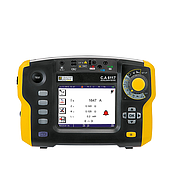
If you have never used this device before, you probably have many questions: How does a waveform generator work? What are the key factors to consider when choosing one? Which models are truly worth investing in? The following information will help you find the right answers.
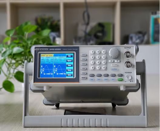
Pulse Generator Overview
A waveform generator, often referred to as a signal generator by many researchers in the electrical and electronic fields, is a device that generates waveform signals such as sine, square, and triangle waves, with adjustable frequency and amplitude. It is an indispensable tool in the research, testing, and development of electrical and electronic systems. In addition to standard waveforms, modern waveform generators support arbitrary waveform generation (AWG), allowing for amplitude and frequency adjustments at different cycles. This capability enables more accurate simulation of complex signals, making them suitable for real-world testing applications. Utilizing digital signal processing (DSP) technology for waveform synthesis, waveform generators typically operate within a frequency range of several MHz to several hundred MHz, with some high-end models reaching a few GHz. The device's output is commonly a BNC port with an impedance of approximately 50–75Ω, ensuring stable signal transmission when connected to other measurement and testing equipment..
Important parameters to know on pulse generator
A waveform generator possesses several key specifications that directly impact its ability to generate and adjust signals. In terms of waveform types, the device can produce sine, square, triangle, sawtooth, pulse, DC, TTL/CMOS signals, or custom waveforms (AWG), catering to a wide range of testing needs. The frequency range of a waveform generator varies depending on the model. Basic models typically operate within 0.05MHz – 5MHz, whereas high-end units can generate signals ranging from several hundred MHz to a few GHz. For input signals, the external voltage level ranges from 0 – 10V, with a modulation ratio of 100:1 and distortion below 1% within the 0.2Hz – 100kHz range. Square wave signals have a minimum rise time and fall time of 25ns, while triangular wave signals maintain linearity between 1% – 5% in the 100kHz – 2MHz range. The TTL output achieves a switching time of 25ns, whereas CMOS takes 40ns. Additionally, waveform generators can operate reliably in temperatures ranging from 0 – 40°C with a maximum humidity of 85% RH. They require a 115/230V DC power supply with a ±10% tolerance and consume approximately 20W. Certain specialized applications may require devices with multiple outputs for combined testing. In such cases, opting for models with dual or multiple outputs enhances cost-effectiveness and efficiency compared to using multiple separate devices. Simple Steps to Use a Waveform Generator To use a waveform generator effectively, start by powering on the device and selecting the appropriate output waveform, such as square, sine, or triangle waves, depending on the test requirements. Next, connect the generator’s output to an oscilloscope to visualize the signal and adjust parameters like frequency and amplitude as needed. This ensures that the generated signal meets the required specifications before applying it to the test circuit. Once the desired settings are configured, connect the waveform generator’s output to the circuit under test. Then, use an oscilloscope or a multimeter to monitor signal variations within the circuit and analyze the results accordingly.
See related articles: Should I buy a pulse generator in 2025?
A few simple steps to use the pulse generator
To use the pulse generator effectively, first turn on the device and select the appropriate output signal type, which can be square wave, sine wave, triangle wave, etc., depending on the test requirements. Next, connect the output of the pulse generator to an oscilloscope to observe the signal and adjust parameters such as frequency and amplitude as needed. This helps ensure that the output signal is correct before being put into the test circuit. Once the desired parameters have been set, connect the output of the pulse generator to the circuit under test. Then, use an oscilloscope or meter to observe the signal changes in the circuit and analyze the results.
Areas of application of pulse generators
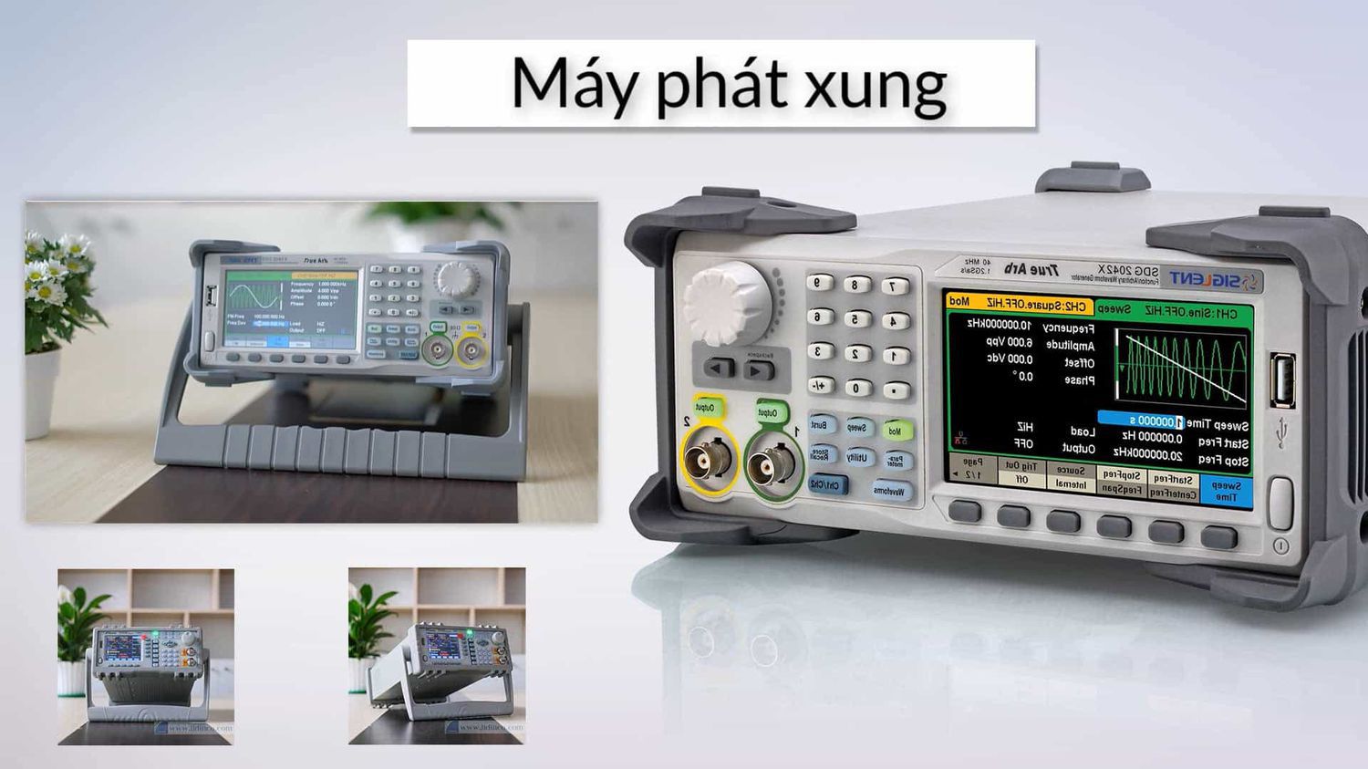
Waveform generators are widely used across various fields due to their ability to create and simulate different signal types. In telecommunications and radio frequency applications, these devices play a crucial role in satellite broadcasting, radar, and radio communications, enabling the simulation of signals with frequencies up to 1.5GHz and supporting wireless bandwidth modulation (BW) standards up to 1GHz. Some models are specifically designed for FM wave generation in the broadcasting industry. In education, waveform generators serve as valuable teaching tools, allowing students to visually examine electronic parameters. This enhances both theoretical understanding and practical application, making learning more effective and engaging. The electronics repair industry also heavily relies on these devices. In repair centers, waveform generators help measure and analyze signals, assisting technicians in accurately diagnosing faults in components and circuits. This significantly improves the speed and accuracy of the repair process. Additionally, waveform generators are extensively used in signal analysis, automotive sensor testing, power line diagnostics, orthogonal frequency-division multiplexing (OFDM) techniques, high-speed serial signal testing, dual-tone multi-frequency (DTMF) systems, and even medical applications such as pacemakers.