Power Factor Capacitors Are Designed for Pure Sinusoidal Voltage
Power factor correction (PFC) capacitors have their lifespan calculated based on the assumption of a pure 50Hz sinusoidal supply voltage. A capacitor's capacitive reactance is inversely proportional to frequency, meaning higher frequencies allow current to flow through the capacitor much more easily. While this characteristic is harmless on a clean sine wave, it turns into a critical vulnerability when high-order harmonics contaminate the power supply.
Harmonics of the 5th and 7th orders and occasionally the 11th and 13th are widespread in industrial plants operating variable frequency drives (VFDs), induction furnaces, and high-power rectifiers. For these high-frequency currents, power factor capacitors act as low-impedance paths, drawing harmonic currents far more aggressively than the fundamental frequency current they were designed to compensate.
You may also be interested in:
Fast and Technically Correct Methods for Testing PFC Capacitors
What Is a PFC Capacitor? Understanding Concepts and Operating Principles
Resonance: The Mechanism Driving Capacitors Beyond Their Limits
An increased harmonic current draw is only part of the problem. When PFC capacitors are connected in parallel with the inductive reactance of transformers or motors, they form an LC resonant circuit. If the resonant frequency of this circuit aligns with or closely matches the frequency of an existing harmonic order in the system, the current at that specific frequency is amplified several times over its baseline value.
This explains why capacitor banks often explode suddenly after a factory adds a few new VFDs or alters its load profile, even if the capacitors ran smoothly for years prior. The resonant point shifts with system configuration changes; once it falls directly onto an active harmonic order, the current flowing through the capacitor surges silently until a bulging casing becomes the only remaining warning sign.
Bulging Casings: The Early Warning Before Catastrophic Failure
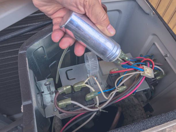
Inside a PFC capacitor, insulating oil or polymer film is wound around internal electrode plates. Over-current conditions generate excessive thermal stress within the capacitor core, causing internal pressure to build over time and forcing the aluminum casing to swell as an early warning sign. Operating continuously in this degraded state eventually leads to dielectric breakdown, triggering internal arcing and an explosive failure mechanism often described by technicians as a capacitor explosion.
Capacitor banks equipped with improperly rated protective fuses or controllers lacking harmonic monitoring functions aggravate these recurring failures, failing to deliver early warnings before severe damage occurs.
Replacing Blown Capacitors Only Continues the Cycle
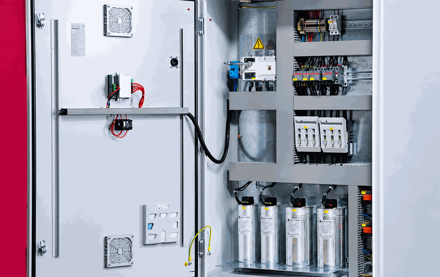
The standard response in many industrial plants is to replace failed capacitors with new ones sometimes even upsizing their capacity rating in hopes of gaining durability. This practice usually extends operational life by only a few months before repeating the exact same failure cycle, because the underlying harmonic resonance within the electrical network remains completely intact, waiting for the next trigger.
To verify whether harmonic resonance exists, maintenance teams must analyze harmonic spectrums for both current and voltage at the capacitor bank coupling point while calculating the actual resonant frequency of the active LC circuit. Standard clamp meters miss this entirely, as they only display a total RMS current value that aggregates all components into a single number.
Critical Parameters to Measure Before Determining the Root Cause
Power Quality Analyzers allow engineers to evaluate Total Harmonic Current Distortion (THD-I) at the capacitor connection point, map energy distribution across harmonic orders to pinpoint dominant components, and identify current amplification at specific frequencies the clearest indicator of active resonance.
Fluke power quality instruments capture voltage and current waveforms simultaneously over extended logging periods. This captures dynamic load shifts throughout the day rather than relying on instantaneous snapshot measurements that risk premature conclusions. For facilities with a history of repeated PFC capacitor failures, comprehensive diagnostic testing is a critical prerequisite before purchasing replacement units or modifying system configurations.
Read more: Overheating Neutral Wires & High Neutral Currents: Causes and Diagnostics
Remediation Strategies for Confirmed Harmonic Resonance
When measurement data confirms that a circuit's resonant frequency overlaps with an active harmonic order, the standard remedy is installing detuning reactors in series with the PFC capacitors (detuned capacitor banks). This shifts the circuit's resonant frequency away from critical harmonic zones. If harmonic distortion levels are exceptionally severe, active or passive harmonic filters should be installed directly at the generating source before harmonic currents reach the capacitor banks.

Selecting the appropriate solution relies directly on empirical measurement data. Because every facility features unique load profiles and resonance points, field experience from other plants serves only as a general reference rather than a direct blueprint.