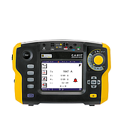
Outstanding advantages of genuine wave machine
Imported oscilloscopes are made from durable, lightweight materials, convenient for moving and operating in lab or field environments. The sharp display shows clear waveforms, helping operators recognize signals in real time.
In addition, high-end models also integrate large touch screens, bandwidths that can reach hundreds of MHz and flexible scanning speeds. Users can easily adjust measurement parameters directly on the display interface or through reasonably arranged physical buttons. Thanks to that, the results obtained are always highly accurate and stable between measurement channels.
Thanks to its mobility and ability to record diverse signals, oscilloscopes are widely used in many fields such as electronics, automation, communications or technical education.
4 Common Errors When Testing Devices Using an Oscilloscope
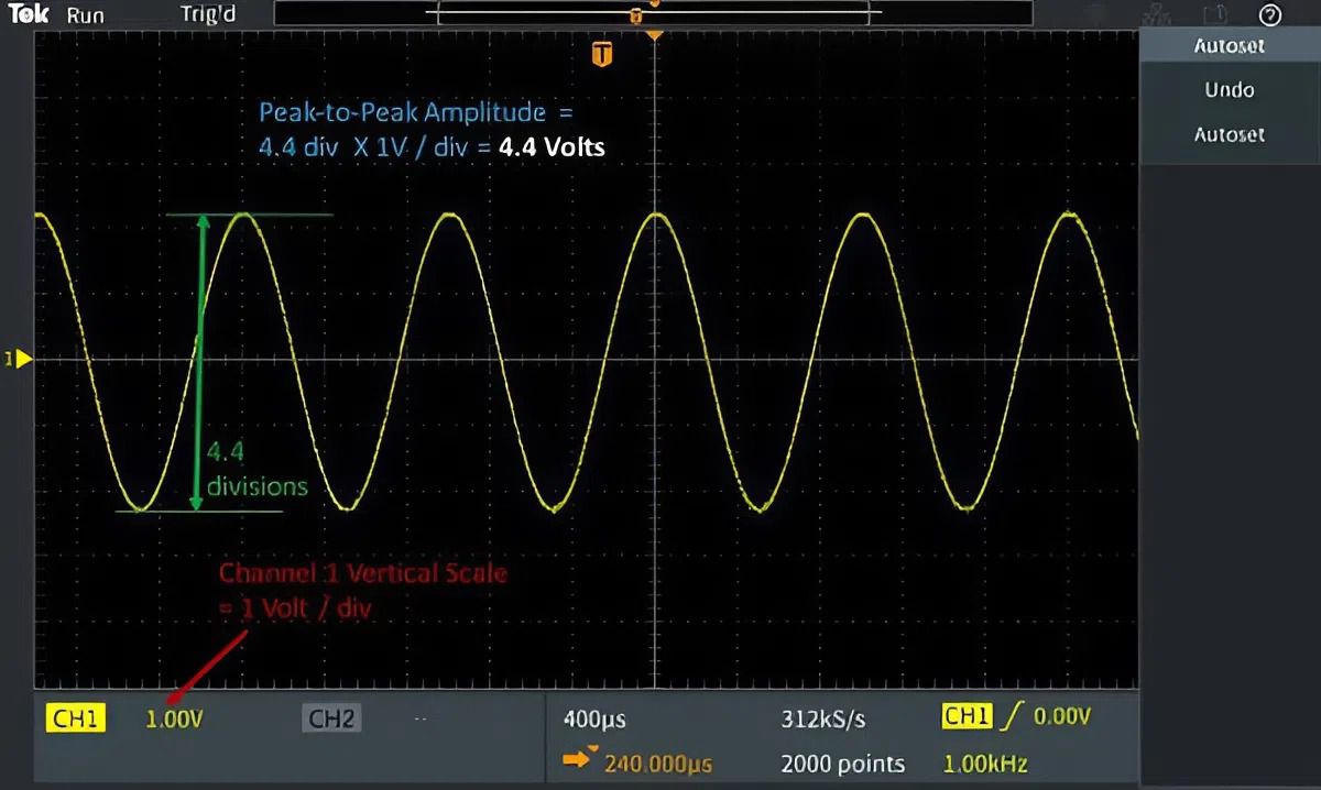
Here are four common errors that engineers can quickly detect and fix with an oscilloscope, along with practical tips for measuring.
1. Unstable voltage fluctuations
In many devices, voltage drops or unusual fluctuations often cause the system to operate erratically and intermittently. When observed with an oscilloscope, you will see that the output wave amplitude is constantly changing instead of staying around a central value.
If the amplitude of the oscillation exceeds the allowable threshold, it is likely that the power circuit is weak or the voltage regulator component is no longer responding. If this type of oscillation is identified early, it will help to localize the faulty area much faster than measuring with a conventional meter.
2. Source noise and filter errors are not completely eliminated
An unclean power supply is often the cause of slight distortion or instability of the signal in the post-processing stage. When fed into an oscilloscope, if the DC waveform still has small periodic ripples, it proves that the filter circuit is not capable of eliminating noise.
The solution is usually to check the filter capacitor and inductor, or increase the capacitor capacity near the load. With control systems, this step is especially important because small noise can cause the microcontroller to reset or cause incorrect control pulses.
3. Loss of oscillation or incorrect frequency
A healthy oscillator circuit must have a stable amplitude and frequency within the allowable range. If the signal appears intermittent or the frequency displayed on the machine deviates significantly from the design, the cause is usually in the oscillator component (crystal, RC, oscillator IC).
The oscilloscope helps to recognize this condition immediately by comparing the actual wave with the standard wave pattern. The engineer does not need to judge but can directly measure each oscillator stage to determine the component causing the deviation.
4. Distorted or distorted signal
Waveform distortion is a common problem in signal amplification. If the output exhibits clipping, wavefront flattening, or phase shift, the circuit may be operating outside the linear range. In this case, the technician should check the bias points of the transistor, op-amp, or output power.
See more related articles:
See now Tip 6 Oscilloscope Tips for Beginners
Getting Familiar with Automated Measurements with Waveforms and Signal Generators?
Oscilloscope Group Control Core and How to Use It
Note for you before connecting to the machine
Before connecting the machine, check whether the probe has been compensated correctly. The initial setting mode should be returned to default, select the 1X factor to observe the 1kHz sample signal. After the waveform is stable, start the actual measurement.
Especially for beginners or when you need to compare multiple measurement channels at the same time.
Above are common errors often encountered when testing and analyzing circuits with an oscilloscope that EMIN wants to share with you. Early detection of abnormal waveforms helps engineers handle problems faster, limit widespread damage and save significant repair time.