The core function of a VFL is to provide a visible red laser beam in the fiber core, allowing technicians to quickly detect and locate abnormal objects on the fiber. The need for a VFL is further reinforced when it is capable of solving problems such as power, macrobends, connector failures, or assisting in fiber identification in multi-core cable bundles, tasks that more complex instruments such as OTDRs duplicate when they have difficulty or cannot perform in their dead zones. To select the optimal VFL, technicians need to be familiar with in-depth technical standards.
The Diverse Applications and Importance of Visual Fault Locator
Beyond its limited use in fault detection, VFLs have many important applications during the construction and maintenance of fiber optic systems. During construction, VFLs assist in checking the quality of mechanical and thermal splices by shining light through the splice to look for light leaks, a sign of high attenuation.
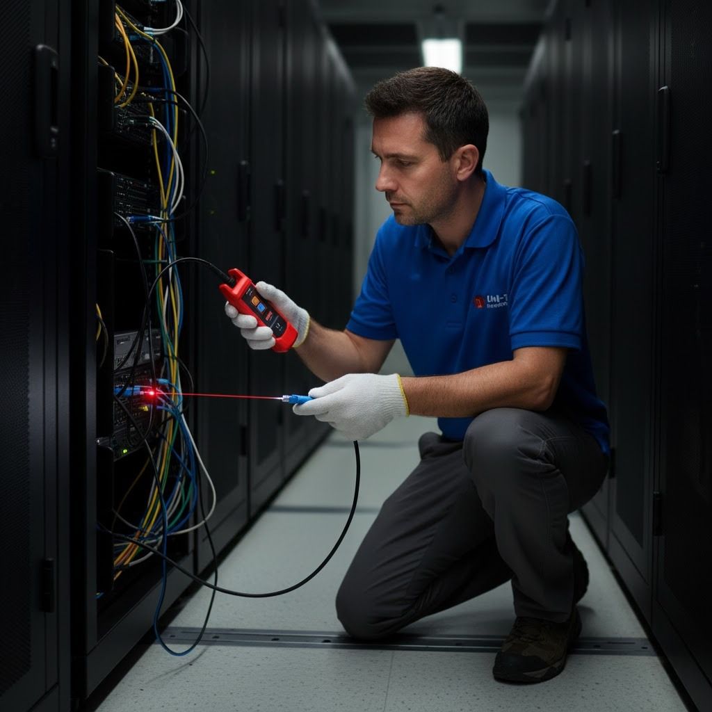
In troubleshooting operations, VFLs are the leading tool for end-to-end identification and short-range fault locating, such as patch cords or pigtails in optical distribution frames (ODFs). The ability to penetrate the thin PVC jacket of the cable to illuminate the fault point makes VFLs a leading time- and cost-saving solution for these tasks.
In-depth Analysis of Technical Criteria When Choosing VFL
The decision to purchase a VFL should be based on a careful analysis of the specifications, ensuring that the equipment meets the specific requirements of the working environment.
Output Power and Its Relationship to Detection Distance
Output power is the most important technical factor of a VFL, directly determining the effective operating range. This power is usually measured in milliwatts (mW). The basic principle is that the higher the power, the stronger the laser light intensity, allowing the light to penetrate thicker cable jackets and reach further distances while still being intense enough to see leaks.
Low Power VFL (under 10mW): Ideal for local area network (LAN) technicians, laboratories, or testing short fiber optic patch cords (a few hundred meters to a few kilometers).
High Power VFL (10mW - 30mW and above): A must-have for telecom and CATV technicians who work on long-haul backbone cables. These high-power models can support single-mode fiber testing up to 10km, even 15km under ideal conditions.
Modulation Frequency and Error Detection
The modulation frequency determines how the laser light is emitted from the VFL. Most modern devices offer two main modes of operation:
Continuous Wave (CW): Emits a steady light. This mode is often used when the VFL is integrated with other measuring devices.
Pulsed Mode (MOD/Pulsed): Emits a low-frequency strobe light (usually 1Hz or 2Hz). This is the preferred mode for practical use. Human vision is much more sensitive to strobe light than steady light, making it easier for technicians to detect red light leaks through cable jacketing or at faulty connections.
Fiber Optic Compatibility and Interface
Technically, VFLs are compatible with both Single-Mode (SM) and Multi-Mode (MM) fiber. However, it should be noted that, because multimode fibers have larger cores (50µm or 62.5µm compared to 9µm for single-mode fibers), VFLs are typically able to couple more light energy into the multimode core, resulting in better detection performance on multimode fibers at the same power level.
In terms of interface, the VFL needs to be able to connect flexibly to a variety of connectors:
Universal 2.5mm Connector: Most VFLs are equipped with outputs compatible with standard FC, SC, and ST connectors.
1.25mm Connector: For high-density connectors such as LC and MU, the technician will need to use an optional 1.25mm adapter.
Physical Design in the Work Environment
The design of the device must be suitable for the nature and harsh working environment.
- Pen-Type VFL: This is a compact, lightweight design, easy to carry with you, suitable for quick and regular inspection work in the house or machine room. However, they often have lower capacity.
- Handheld VFLs: These devices are typically larger, can have higher power, and are designed with a more rugged, impact- and dust-resistant housing. They are ideal for technicians working outdoors, on construction sites, or on telecommunication cables.
You can refer to the optical fault locator products in our catalog: Optical fault locator
Necessary VFL Maintenance and Precautions
Proper use and maintenance of VFLs is paramount to protect the equipment and the operator.
- Laser Safety: This is the ultimate rule. Never look directly into an active laser beam or fiber optic tip, as laser light, including visible red light, can cause serious and permanent damage to the retina.
- Cleanliness: Always keep the VFL laser head and the end face of the fiber connector clean. Dust and dirt can cause significant light loss, reducing the effective detection distance.
- Electrical Precautions: Do not connect the VFL to any active optoelectronic device or microscope. Always ensure that the opposite end of the fiber is disconnected from any device.
- Battery Care: Remove the battery from the device if the VFL is not used for a long time to avoid battery leakage and damage to the electronic circuit.
These are the trade-offs between Output Power, Pulse Mode of Operation, Connector Compatibility and Mechanical Durability to optimize troubleshooting performance in any application environment, from local area networks to complex telecommunications networks.